DESIGNING ELECTRONIC CIRCUITS WITH FORMULAS
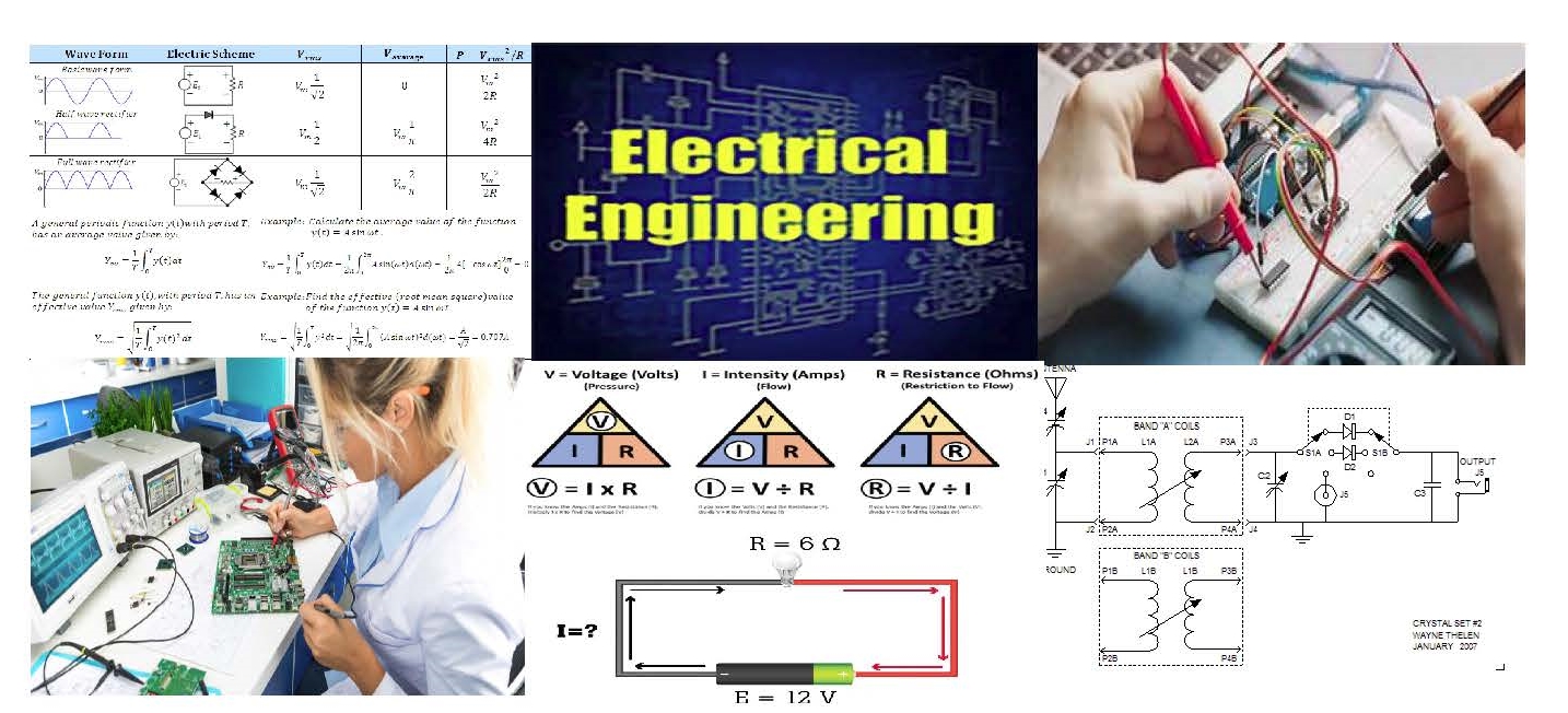
An engineering discipline that deals with the study and / or application of electricity, electronics, and electromagnetism and covering a range of sub-studies including those that deal with power, electronics, control systems, signal processing and telecommunications.
Well that's a dictionary attempt at explaining the science of electrical engineering, however, I more recently have been reviewing a professor of electrical engineering who derived a simpler and more understandable definition. Electrical engineering is the science of creating of one circuit that operates another circuit.
There is no way, I am going to write let alone explain all the formula used in electrical engineering classes or in the field, but we will explore Ohms Law (its not actually a law) and then design circuits. The object here is to expose anyone who is interested the practical application of circuits we use in our daily life. Building on these principals there is no reason why you can not adopt the circuits here to operate equipment that I have not thought of.
There are several contributors over the years to the study of electronics, one of the first modern scientists was Michael Farraday, he was an English scientist who contributed to the study of electromagnetism and electrochemistry. His main discoveries include the principles underlying electromagnetic induction, diamagnetism and electrolysis. Next in the series is Nikola Tesla who's contributions include the development of an induction motor that ran on alternating current (AC), a power system format and at that time was rapidly expanding in Europe and the United States because of its advantages in long-distance, high-voltage transmission. The motor used polyphase current, which generated a rotating magnetic field to turn the motor (a principle that Tesla claimed to have conceived in 1882. In the summer of 1889, Tesla traveled to the 1889 Exposition Universelle in Paris and learned of Heinrich Hertz's 1886–88 experiments that proved the existence of electromagnetic radiation, including radio waves. Last but certainly not least is our own Tom Edison. Edison gave us the incandescent light bulb and proclamed DC power would illuminate the world. His idea was not incorrect, but there was a better way to produce electricity to the community than by DC current. Tesla gave us the induction motor, (the generator) and introduced the world to AC current. The saving grace was not the discovery of AC current but the transformer, without which we would still be on the DC circuit.
We will be using AC as well as DC and electromagnetic induction. Most of our modern appliances like the flat screen TV, your cell phone, radios, and in fact most of all our appliances use DC electronic circuitry to operate our appliances. We will explore how to convert AC to DC for our circuitry. A transistor can not handle 120 VAC to operate circuits they require DC power.
Now if you want food for thought, we know that we can store DC voltage in a battery. Your automobile is a good example. The car battery can store 12 VDC for long periods of time. That battery is a result of a chemical reaction with metals inside the battery which produce DC current. If you want to be the next millionaire invent a device that can hold AC voltage like a battery. That device has stumped electrical engineers since the discovery of AC current.
Enough for the history of electronics, let's get started with the devises that we will employ in building our circuitry and the formula(s) that allow us to understand the functionality of the circuits.
Before we start, I think a brief look at the components that we will be utilizing in designing the circuits is appropriate. The below chart describes the most used schematic symbols to view a complete symbol identification chart click on the component link.
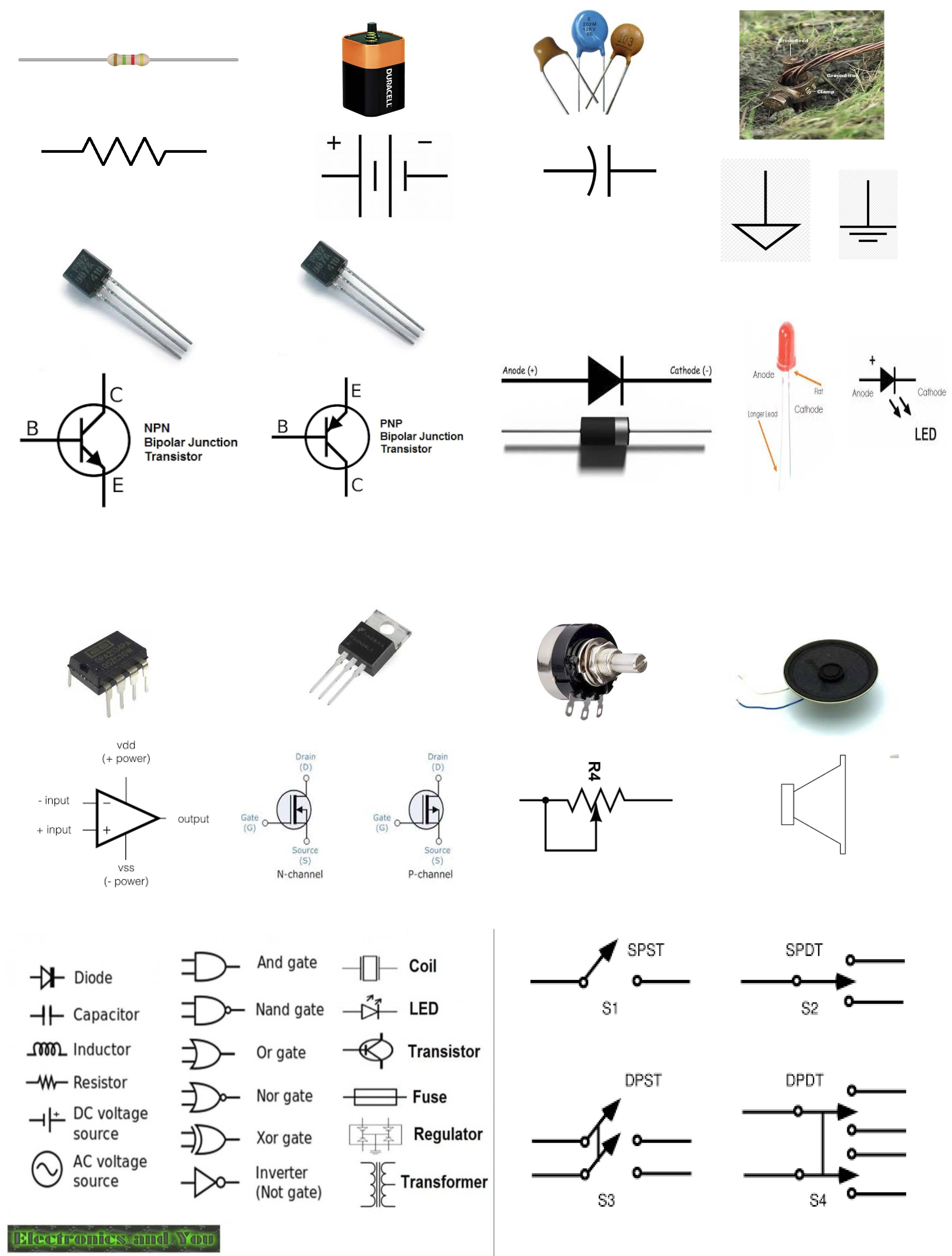
HERE IS THE COMPLETE TABLE OF COMPONENTS
Now that we have a working knowledge of the components, we will construct circuits. The first circuit will be centered around Ohm's Law, (its not actually a law but everyone calls it that). The following are the three formulas that comprise Ohm's Law.
Where:
I = Current in Amperes - sometimes we use W in VAC applications, but for our applications we will use ' I '
V = Voltage VDC (Volts Direct Current)
R = Resistance in Ohms or Ω
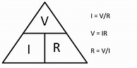
Even if you forget the formulas remember the above tirangle. To arrive at the value just cover the symbol, so if you want to know the voltage cover the ' V ' and you see that voltage = I x R. Likewise covering 'R' we see that Resistance = Volts / I current.
We will be using Ohm's law in determining the necessary values for capacitors and resistors. A review of the math for determining total resistance in both parallel and series resistors.
Resistors in Parallel Example No1
The five resistive networks above may look different to each other, but they are all arranged as Resistors in Parallel and as such the same conditions and equations apply.
Find the total resistance, RT of the following resistors connected in a parallel network.
The total resistance RT across the two terminals A and B is calculated as:
This method of reciprocal calculation can be used for calculating any number of individual resistances connected together within a single parallel network. If however, there are only two individual resistors in parallel then we can use a much simpler and quicker formula to find the total or equivalent resistance value, RT and help reduce the reciprocal maths a little. This much quicker product-over-sum method of calculating two resistor in parallel, either having equal or unequal values is given as:
Resistors in Parallel Example No2
Consider the following circuit which has only two resistors in a parallel combination.

Using our formula above for two resistors connected together in parallel we can calculate the total circuit resistance, RT as:

One important point to remember about resistors in parallel, is that the total circuit resistance ( RT ) of any two resistors connected together in parallel will always be LESS than the value of the smallest resistor in that combination.
In our example above, the value of the combination was calculated as: RT = 15kΩ, where as the value of the smallest resistor is 22kΩ, much higher. In other words, the equivalent resistance of a parallel network will always be less than the smallest individual resistor in the combination.
Also, in the case of R1 being equal to the value of R2, that is R1 = R2, the total resistance of the network will be exactly half the value of one of the resistors, R/2.
Likewise, if three or more resistors each with the same value are connected in parallel, then the equivalent resistance will be equal to R/n where R is the value of the resistor and n is the number of individual resistances in the combination.
For example, six 100Ω resistors are connected together in a parallel combination. The equivalent resistance will therefore be: RT = R/n = 100/6 = 16.7Ω. But note that this ONLY works for equivalent resistors. That is resistors all having the same value.
Currents in a Parallel Resistor Circuit
The total current, IT entering a parallel resistive circuit is the sum of all the individual currents flowing in all the parallel branches. But the amount of current flowing through each parallel branch may not necessarily be the same, as the resistive value of each branch determines the amount of current flowing within that branch.
For example, although the parallel combination has the same voltage across it, the resistances could be different therefore the current flowing through each resistor would definitely be different as determined by Ohms Law.
Consider the two resistors in parallel above. The current that flows through each of the resistors ( IR1 and IR2 ) connected together in parallel is not necessarily the same value as it depends upon the resistive value of the resistor. However, we do know that the current that enters the circuit at point A must also exit the circuit at point B.
Kirchhoff’s Current Laws states that: “the total current leaving a circuit is equal to that entering the circuit – no current is lost“. Thus, the total current flowing in the circuit is given as:
IT = IR1 + IR2
Then by using Ohm’s Law, the current flowing through each resistor of Example No2 above can be calculated as:
Current flowing in R1 = VS ÷ R1 = 12V ÷ 22kΩ = 0.545mA or 545μA
Current flowing in R2 = VS ÷ R2 = 12V ÷ 47kΩ = 0.255mA or 255μA
thus giving us a total current IT flowing around the circuit as:
IT = 0.545mA + 0.255mA = 0.8mA or 800μA
and this can also be verified directly using Ohm’s Law as:
IT = VS ÷ RT = 12 ÷ 15kΩ = 0.8mA or 800μA (the same)
The equation given for calculating the total current flowing in a parallel resistor circuit which is the sum of all the individual currents added together is given as:
Itotal = I1 + I2 + I3 ….. + In
Then parallel resistor networks can also be thought of as “current dividers” because the supply current splits or divides between the various parallel branches. So a parallel resistor circuit having N resistive networks will have N-different current paths while maintaining a common voltage across itself. Parallel resistors can also be interchanged with each other without changing the total resistance or the total circuit current.
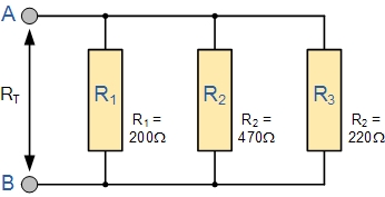
Resistors in Parallel Example No3
Calculate the individual branch currents and total current drawn from the power supply for the following set of resistors connected together in a parallel combination.

As the supply voltage is common to all the resistors in a parallel circuit, we can use Ohms Law to calculate the individual branch current as follows.

Then the total circuit current, IT flowing into the parallel resistor combination will be:

This total circuit current value of 5 amperes can also be found and verified by finding the equivalent circuit resistance, RT of the parallel branch and dividing it into the supply voltage, VS as follows.
Equivalent circuit resistance:

Then the current flowing in the circuit will be:

Resistors in Parallel Summary
So to summarize, when two or more resistors are connected so that both of their terminals are respectively connected to each terminal of the other resistor or resistors, they are said to be connected together in parallel. The voltage across each resistor within a parallel combination is exactly the same but the currents flowing through them are not the same as this is determined by their resistance value and Ohms Law. Then parallel circuits are current dividers.
The equivalent or total resistance, RT of a parallel combination is found through reciprocal addition and the total resistance value will always be less than the smallest individual resistor in the combination. Parallel resistor networks can be interchanged within the same combination without changing the total resistance or total circuit current. Resistors connected together in a parallel circuit will continue to operate even though one resistor may be open-circuited.
Thus far we have seen resistor networks connected in either a series or a parallel combination. In the next tutorial about Resistors, we will look at connecting resistors together in both a series and parallel combination at the same time producing a mixed or combinational resistor circuit.
Series Resistor Circuit

As the resistors are connected together in series the same current passes through each resistor in the chain and the total resistance, RT of the circuit must be equal to the sum of all the individual resistors added together. That is
![]()
and by taking the individual values of the resistors in our simple example above, the total equivalent resistance, REQ is therefore given as:
REQ = R1 + R2 + R3 = 1kΩ + 2kΩ + 6kΩ = 9kΩ

So we see that we can replace all three individual resistors above with just one single “equivalent” resistor which will have a value of 9kΩ.
Where four, five or even more resistors are all connected together in a series circuit, the total or equivalent resistance of the circuit, RT would still be the sum of all the individual resistors connected together and the more resistors added to the series, the greater the equivalent resistance (no matter what their value).
This total resistance is generally known as the Equivalent Resistance and can be defined as; “a single value of resistance that can replace any number of resistors in series without altering the values of the current or the voltage in the circuit“. Then the equation given for calculating total resistance of the circuit when connecting together resistors in series is given as:
Series Resistor Equation
Rtotal = R1 + R2 + R3 + ….. Rn etc.
Note then that the total or equivalent resistance, RT has the same effect on the circuit as the original combination of resistors as it is the algebraic sum of the individual resistances.
|
|
If two resistances or impedances in series are equal and of the same value, then the total or equivalent resistance, RT is equal to twice the value of one resistor. That is equal to 2R and for three equal resistors in series, 3R, etc. |

|
|
If two resistors or impedances in series are unequal and of different values, then the total or equivalent resistance, RT is equal to the mathematical sum of the two resistances. That is equal to R1 + R2. If three or more unequal (or equal) resistors are connected in series then the equivalent resistance is: R1 + R2 + R3 +…, etc. |

One important point to remember about resistors in series networks to check that your maths is correct. The total resistance ( RT ) of any two or more resistors connected together in series will always be GREATER than the value of the largest resistor in the chain. In our example above RT = 9kΩ where as the largest value resistor is only 6kΩ.
Series Resistor Voltage
The voltage across each resistor connected in series follows different rules to that of the series current. We know from the above circuit that the total supply voltage across the resistors is equal to the sum of the potential differences across
R1 , R2 and R3 , VAB = VR1 + VR2 + VR3 = 9V.
Using Ohm’s Law, the voltage across the individual resistors can be calculated as:
Voltage across R1 = IR1 = 1mA x 1kΩ = 1V
Voltage across R2 = IR2 = 1mA x 2kΩ = 2V
Voltage across R3 = IR3 = 1mA x 6kΩ = 6V
giving a total voltage VAB of ( 1V + 2V + 6V ) = 9V which is equal to the value of the supply voltage. Then the sum of the potential differences across the resistors is equal to the total potential difference across the combination and in our example this is 9V.
The equation given for calculating the total voltage in a series circuit which is the sum of all the individual voltages added together is given as:
![]()
Then series resistor networks can also be thought of as “voltage dividers” and a series resistor circuit having N resistive components will have N-different voltages across it while maintaining a common current.
By using Ohm’s Law, either the voltage, current or resistance of any series connected circuit can easily be found and resistor of a series circuit can be interchanged without affecting the total resistance, current, or power to each resistor.
Resistors in Series Example No1
Using Ohms Law, calculate the equivalent series resistance, the series current, voltage drop and power for each resistor in the following resistors in series circuit.

All the data can be found by using Ohm’s Law, and to make life a little easier we can present this data in tabular form.
| Resistance | Current | Voltage | Power |
| R1 = 10Ω | I1 = 200mA | V1 = 2V | P1 = 0.4W |
| R2 = 20Ω | I2 = 200mA | V2 = 4V | P2 = 0.8W |
| R3 = 30Ω | I3 = 200mA | V3 = 6V | P3 = 1.2W |
| RT = 60Ω | IT = 200mA | VS = 12V | PT = 2.4W |
Then for the circuit above, RT = 60Ω, IT = 200mA, VS = 12V and PT = 2.4W
The Voltage Divider Circuit
We can see from the above example, that although the supply voltage is given as 12 volts, different voltages, or voltage drops, appear across each resistor within the series network. Connecting resistors in series like this across a single DC supply has one major advantage, different voltages appear across each resistor producing a very handy circuit called a Voltage Divider Network.
This simple circuit splits the supply voltage proportionally across each resistor in the series chain with the amount of voltage drop being determined by the resistors value and as we now know, the current through a series resistor circuit is common to all resistors. So a larger resistance will have a larger voltage drop across it, while a smaller resistance will have a smaller voltage drop across it.
The series resistive circuit shown above forms a simple voltage divider network were three voltages 2V, 4V and 6V are produced from a single 12V supply. Kirchhoff’s Voltage Law states that “the supply voltage in a closed circuit is equal to the sum of all the voltage drops (I*R) around the circuit” and this can be used to good effect.
The Voltage Division Rule, allows us to use the effects of resistance proportionality to calculate the potential difference across each resistance regardless of the current flowing through the series circuit. A typical “voltage divider circuit” is shown below.
Voltage Divider Network

The circuit shown consists of just two resistors, R1 and R2 connected together in series across the supply voltage Vin. One side of the power supply voltage is connected to resistor, R1, and the voltage output, Vout is taken from across resistor R2. The value of this output voltage is given by the corresponding formula.
If more resistors are connected in series to the circuit then different voltages will appear across each resistor in turn with regards to their individual resistance R (Ohms Law I*R) values providing different but smaller voltage points from one single supply.
So if we had three or more resistances in the series chain, we can still use our now familiar potential divider formula to find the voltage drop across each one. Consider the circuit below.

The potential divider circuit above shows four resistances connected together is series. The voltage drop across points A and B can be calculated using the potential divider formula as follows:

We can also apply the same idea to a group of resistors in the series chain. For example if we wanted to find the voltage drop across both R2 and R3 together we would substitute their values in the top numerator of the formula and in this case the resulting answer would give us 5 volts (2V + 3V).
In this very simple example the voltages work out very neatly as the voltage drop across a resistor is proportional to the total resistance, and as the total resistance, (RT) in this example is equal to 100Ω or 100%, resistor R1 is 10% of RT, so 10% of the source voltage VS will appear across it, 20% of VS across resistor R2, 30% across resistor R3, and 40% of the supply voltage VS across resistor R4. Application of Kirchhoff’s voltage law (KVL) around the closed loop path confirms this.
Now lets suppose that we want to use our two resistor potential divider circuit above to produce a smaller voltage from a larger supply voltage to power an external electronic circuit. Suppose we have a 12V DC supply and our circuit which has an impedance of 50Ω requires only a 6V supply, half the voltage.
Connecting two equal value resistors, of say 50Ω each, together as a potential divider network across the 12V will do this very nicely until we connect the load circuit to the network. This is because the loading effect of resistor RL connected in parallel across R2 changes the ratio of the two series resistances altering their voltage drop and this is demonstrated below.
Resistors in Series Example No2
Calculate the voltage drops across X and Y
a) Without RL connected
b) With RL connected

As you can see from above, the output voltage Vout without the load resistor connected gives us the required output voltage of 6V but the same output voltage at Vout when the load is connected drops to only 4V, (Resistors in Parallel).
Then we can see that a loaded voltage divider network changes its output voltage as a result of this loading effect, since the output voltage Vout is determined by the ratio of R1 to R2. However, as the load resistance, RL increases towards infinity (∞) this loading effect reduces and the voltage ratio of Vout/Vs becomes unaffected by the addition of the load on the output. Then the higher the load impedance the less is the loading effect on the output.
The effect of reducing a signal or voltage level is known as Attenuation so care must be taken when using a voltage divider network. This loading effect could be compensated for by using a potentiometer instead of fixed value resistors and adjusted accordingly. This method also compensates the potential divider for varying tolerances in the resistors construction.
A variable resistor, potentiometer or pot as it is more commonly called, is a good example of a multi-resistor voltage divider within a single package as it can be thought of as thousands of mini-resistors in series. Here a fixed voltage is applied across the two outer fixed connections and the variable output voltage is taken from the wiper terminal. Multi-turn pots allow for a more accurate output voltage control.
The Voltage Divider Circuit is the simplest way of producing a lower voltage from a higher voltage, and is the basic operating mechanism of the potentiometer.
As well as being used to calculate a lower supply voltage, the voltage divider formula can also be used in the analysis of more complex resistive circuits containing both series and parallel branches. The voltage or potential divider formula can be used to determine the voltage drops around a closed DC network or as part of a various circuit analysis laws such as Kirchhoff’s or Thevenin’s theorems.
Applications of Resistors in Series
We have seen that Resistors in Series can be used to produce different voltages across themselves and this type of resistor network is very useful for producing a voltage divider network. If we replace one of the resistors in the voltage divider circuit above with a Sensor such as a thermistor, light dependant resistor (LDR) or even a switch, we can convert an analogue quantity being sensed into a suitable electrical signal which is capable of being measured.
For example, the following thermistor circuit has a resistance of 10KΩ at 25°C and a resistance of 100Ω at 100°C. Calculate the output voltage (Vout) for both temperatures.
Thermistor Circuit

At 25°C

At 100°C

So by changing the fixed 1KΩ resistor, R2 in our simple circuit above to a variable resistor or potentiometer, a particular output voltage set point can be obtained over a wider temperature range.
Resistors in Series Summary
So to summarize, when two or more resistors are connected together end-to-end in a single branch, the resistors are said to be connected together in series. Resistors in Series carry the same current, but the voltage drop across them is not the same as their individual resistance values will create different voltage drops across each resistor as determined by Ohm’s Law ( V = I*R ). Then series circuits are voltage dividers.
In a series resistor network the individual resistors add together to give an equivalent resistance, ( RT ) of the series combination. The resistors in a series circuit can be interchanged without affecting the total resistance, current, or power to each resistor or the circuit.
In the next tutorial about Resistors, we will look at connecting resistors together in parallel and show that the total resistance is the reciprocal sum of all the resistors added together and that the voltage is common to a parallel circuit.
Capacitors in Series and Parallel
Systems including capacitors more than one has equivalent capacitance. Capacitors can be connected to each other in two ways. They can be connected in series and in parallel. We will see capacitors in parallel first.
In this circuit capacitors are connected in parallel.

Because, left hand sides of the capacitors are connected to the potential a, and right hand sides of the capacitors are connected to the potential b. In other words we can say that each capacitor has same potential difference. We find the charge of each capacitor as;
Q1=C1.V
Q2=C2.V
Q3=C3.V
Total charge of the system is found by adding up each charge.
Qtotal=Ceq.V
Qtotal= Q1+Q2+Q3=C1.V+C2.V+C3.V=V.(C1+C2+C3)=Ceq
Ceq=C1+C2+C3
As you can see, we found the equivalent capacitance of the system as C1+C2+C3
Now we will see the capacitors in series;

In capacitors in series, each capacitor has same charge flow from battery. In this circuit, +Q charge flows from the positive part of the battery to the left plate of the first capacitor and it attracts –Q charge on the right plate, with the same idea, -Q charge flows from the battery to the right plate of the third capacitor and it attracts +Q on the left plate. Other capacitors are also charged with same way. To sum up we can say that each capacitor has same charge with batter.
C1.V1=Q
C2.V2=Q , V=V1+V2+V3 and Q=Ceq.V
C3.V3=Q


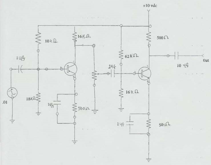
Now to the meat and potatoes of this area, we are going to design a Non-Inverted Op Amp. The below schematic was drawn on a free site namely:
This will bring you to the actual schematic I drew on this page. You can design your own schematics. If you want you can also try the following design applications but you might have to pay a fee to use it. The first site is www.circuitlab.com It is comprehensive and gives you the opportunity to run your design. Another design application is also available and it gives you the opportunity not only to run your design but to use an oscilloscope to see your output waves. It is located at the following URL www.DoCircuits.com
Her is my design of the transistor versions of the Op Amp with values added.
Best advice - Don't build it BUY IT - All this above circuitry is contained in an IC
So, just buy an IC that is an OPAmp. Connect it to the power source and it will do exactly what we have just created. Believe it or not, here is the actual IC Opamp in the design schematic and it works just like the one above, without the hassle.
MORE TO COME JUST STAND BY