ELECTRIC AND ELECTRONIC FORMULAS
The best way to begin this series is to start with the difference between Electric circuitry and Electronic circuitry. Electrical circuitry is that circuitry with a combination of voltage source(s), conductors, insulators, transformers, switches and in most instances a safety valve (a fuse) or circuit breaker that have the ability to operate an appliance. There are three forms of electricity, we are going to investigate only two. The AC current and DC current. Historically, when Edison began utilizing electricity for illumination of his light bulb invention, he used DC voltage. During that same period of time another inventor Tesla postulate that AC current was more efficient over long transmission lines.
AC replaced DC chiefly for one reason: the transformer. This is the device that can use electric power at one potential to produce an equal amount of power at another potential.
Starting in the late 1880s, Edison developed a cost-effective means of generating DC electricity, and a number of related devices, including motors and meters to measure DC energy consumed. However, there was a problem. There was no way back then to convert the DC voltage to higher or lower values. To be safe for use in homes and factories, the DC generators were designed to produce electricity at low voltages. The downside was that this meant the losses during transmission from the generator to the consumer were high. Edison judged that to be an acceptable compromise, but it limited the distance between the generator and consumers to less than a kilometer or two. In practice, Edison would have had to put a DC generator every few miles to accomplish the necessary voltages needed to operate his lights.
In the other camp, Tesla had a secret weapon known as the transformer. It is a simple arrangement of iron cores and copper windings that allows voltage to be converted up or down. The limitation is that transformers only work with AC electricity.
With transformers, Tesla could boost the generator output to thousands of volts for low-loss transmission over long distances then cut the voltage down again to safe values for final delivery to the consumer.
Without getting too deep into the weeds of the formula for transformers, suffice it to say that a transformer is a device that is constructed around a square or an oblong iron core with two sets of wires wound around each side of the core. Look at the below picture to visualize what Tesla did to create his transformer.
![]()
Now how it works. AC electricity is fed into it on the primary side, this AC power is indicated by the circle with the Sine wave ~ in the center. In the transformer every turn of wire whether in the input coil (the primary) or the secondary, encloses the same magnetic flux. Therefore there is a potential. A transformer can increase (step up) or decrease (step down) potentials strictly according to the relative number of turns in the two coils. Some transformers have several secondaries,so that a number of different potentials can be obtained in the output. Here is the genius of the transformer. As you step up the winding on the secondary (Stepping up the output voltage) the Current decreases. Therefore preventing line loss.
Somewhere in your community there is a transformer substation that receives the 235,000 volt power and steps it down to about 13,800 volts. The current travels locally for short distances, either on overhead poles or underground. Now without the transformer, the voltage from the power company would enter your home at a very high voltage say 1,000 volts. No one wants a potential difference of 1,000 volts, it's too dangerous. The transformer comes to the rescue. Transformers with more winding on the primary side and less on the secondary side reduces the voltage and increases the current.
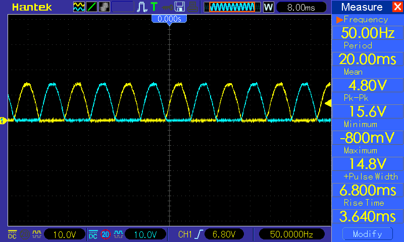
Therefore for long distance power to arrive at your home, the power company generated hundreds of Kilowatts of power to the substation, which steps it down to 13,000+ AC Voltage and sends it along to your neighborhood where another transformer steps that voltage down to 240 Volts AC. The transmission lines, not to get into 3 phase electricity, comes in pairs of 120 VAC on each line, which is the usable AC voltage to your home. Actually, the voltage is about 170 VAC but the RMS voltage in your home is about 120 VAC. If you look at an oscilloscope with a 120 VAC input, the sine wave will show several voltages. Below is an picture of an oscilloscope tracing of the AC power into your home:
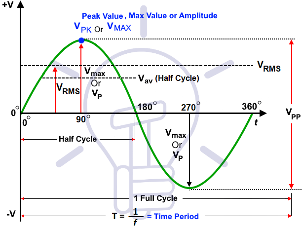
The Peak voltage coming into you home is about 170 VAC, however, if you check your wall outlet with an AC Voltmeter, you will find that the RMS voltage is about 120 VAC. The sine wave goes both positive above he 0 axis and negative below the 0 axis. DC voltage only has a tracing in the positive area.
With AC voltage one needs to use a conductor that can handle 120 VAC at 60 Cycles. That's household electric. Now electricity is a combination of Voltage which is the pressure pushing the electrons along the conductor (wire) and the Amperage (current) is the amount or number of electrons that pass a given point in one second. Wattage (the amount of power required to operate an electrical appliance or device).
The formula is W = V x A
So for example we have an electrical appliance that requires 1000 watts to operate, something like an clothes iron. If we plug that into a wall outlet that not connected to another appliance, we see that the voltage of 120 volts x the 15 Amp fuse (or circuit breaker) = 1,800 available Watts. So the iron will work without blowing or tripping the breaker.
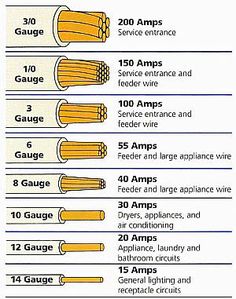
Now suppose we have an appliance that requires 2000 watts or have two appliances each needing 1000 watts each, what will happen once you turn on both appliances in this circuit. Well, the draw of wattage is more than the line can handle, so the fuse or breaker will shut off the electric to continuing along the wires. Since heat is generated by the flow of electrons, if the wire is too small to handle all that power it will melt or potentially cause a fire. For those appliances that require more wattage you have to increase the amount of Amperage permitted in the circuit. But you must use a wire that can handle the power. Increasing Amperage requires you wire that outlet with the below approved wire sizes:
Before we get to the DC circuits, I want to advise you that if you choose to wire your own duplex outlets you might need to obtain an electrical permit from your local build inspector. If you do not feel comfortable around electricity, hire a licensed electrician.
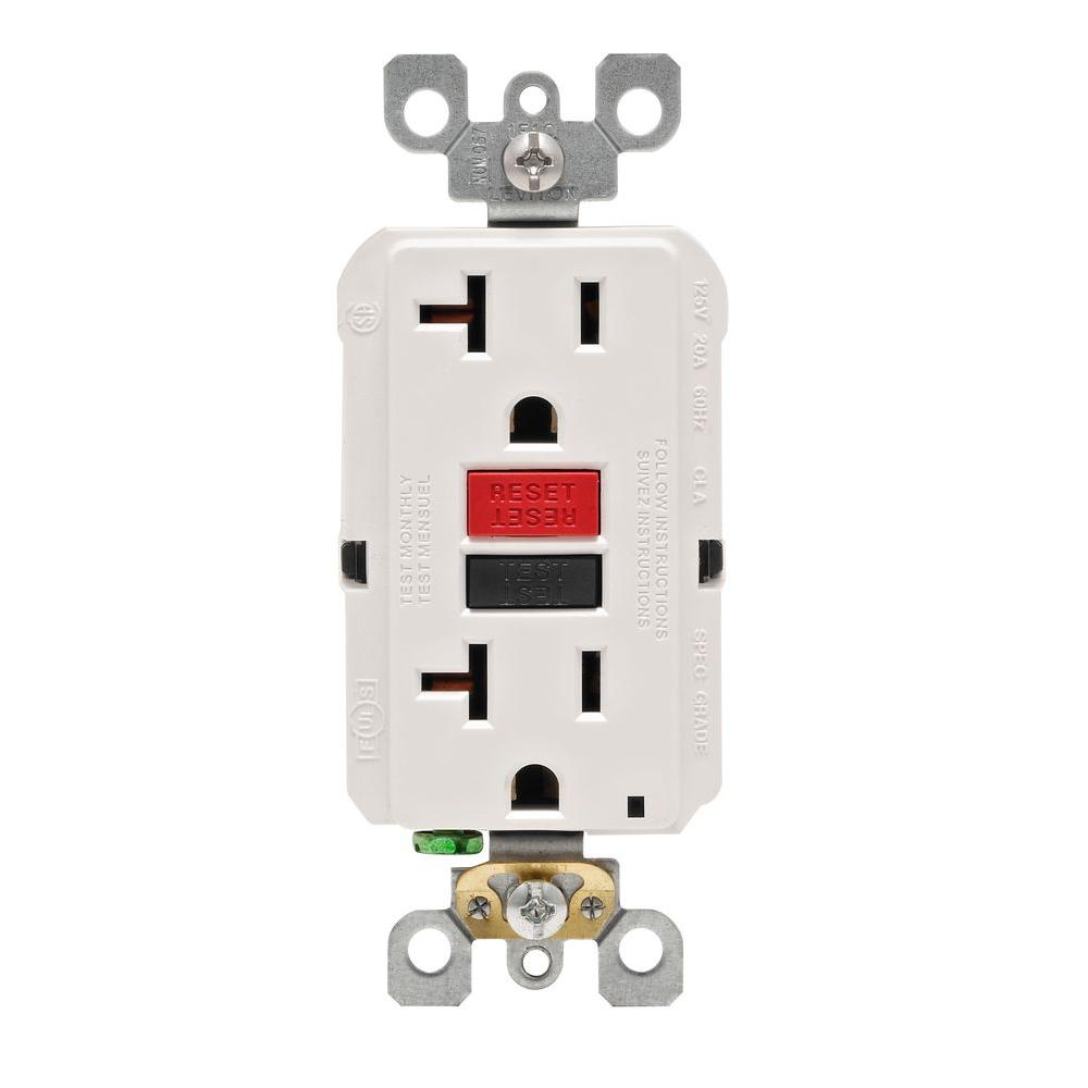
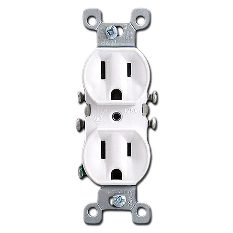
If you do choose to wire your own duplex outlets, make sure they are properly grounded. The duplex outlet can be either a ground fault type or a regular 3 prong duplex outlet like the ones below. The first outlet is a ground fault duplex outlet. They are normally used in areas like the kitchen or bathroom or near a pool, however, the way they work prevents shock be cutting off the electric to the outlet immediately. The other outlet on the right side is a regular duplex outlet normally wired in the home.
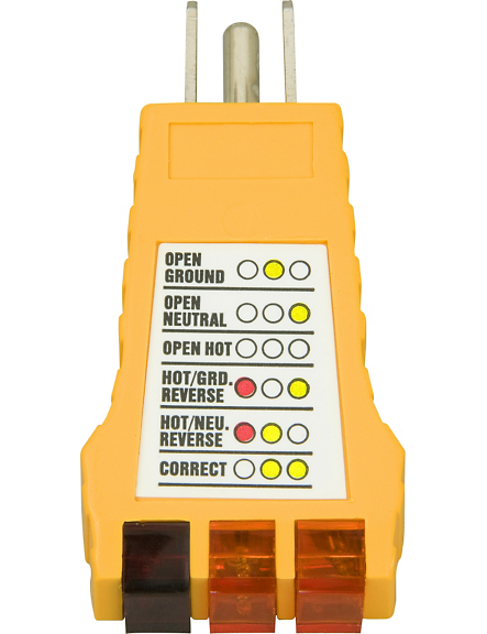
Now since you chose the outlet, make sure you wire it correctly. There is a device that tests the circuit to make sure you wired it correctly. Oddly enough the electrical inspector uses the same device to approve the house wiring completed by an electrician. That device is shown below:
- The white "neutral" wire - this wire is connected to the silver screw on the electrical receptacle, often labeled "neutral" or "white". You can see our white neutral wire connected to a silver screw on the receptacle in our photo.
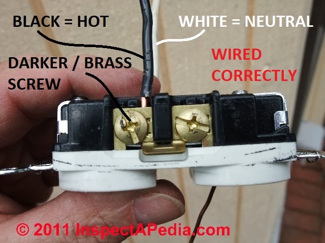
- The black "hot" wire - this wire is fed from the circuit breaker to deliver power to the receptacle, and it connects to the brass or bronze-colored screw on the receptacle, often labeled "hot" or "live" or "black" (or "red" in some situations).
If you want to see a video of how its done double click the following link: https://youtu.be/DTQsqO7_Tr0
So much for the AC model. Now onto DC electricity. We are probably more familiar with the battery model of DC current. Most household batteries fall into the 1.5 DC Voltage range, scripted as 1.5 VDC. Your car battery on the other hand has 12 VDC and stores voltage and is commonly referred to as a storage battery, or an Acid-Lead battery due to is composition.
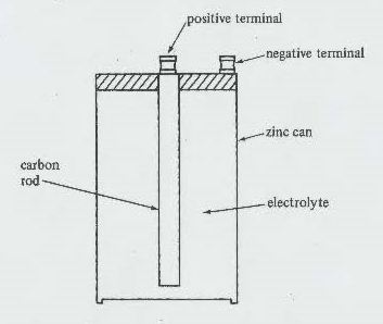
Below we have a picture of an older style battery, which in the 50's and 60's one would purchase for their project(s). Since it is somewhat larger than the current penlight AAA batteries I chose it for demonstration purposes. Here it is:
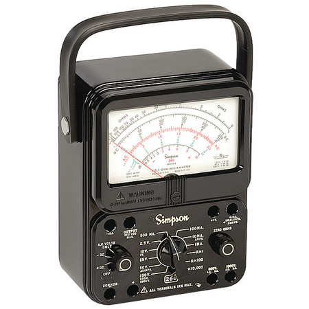
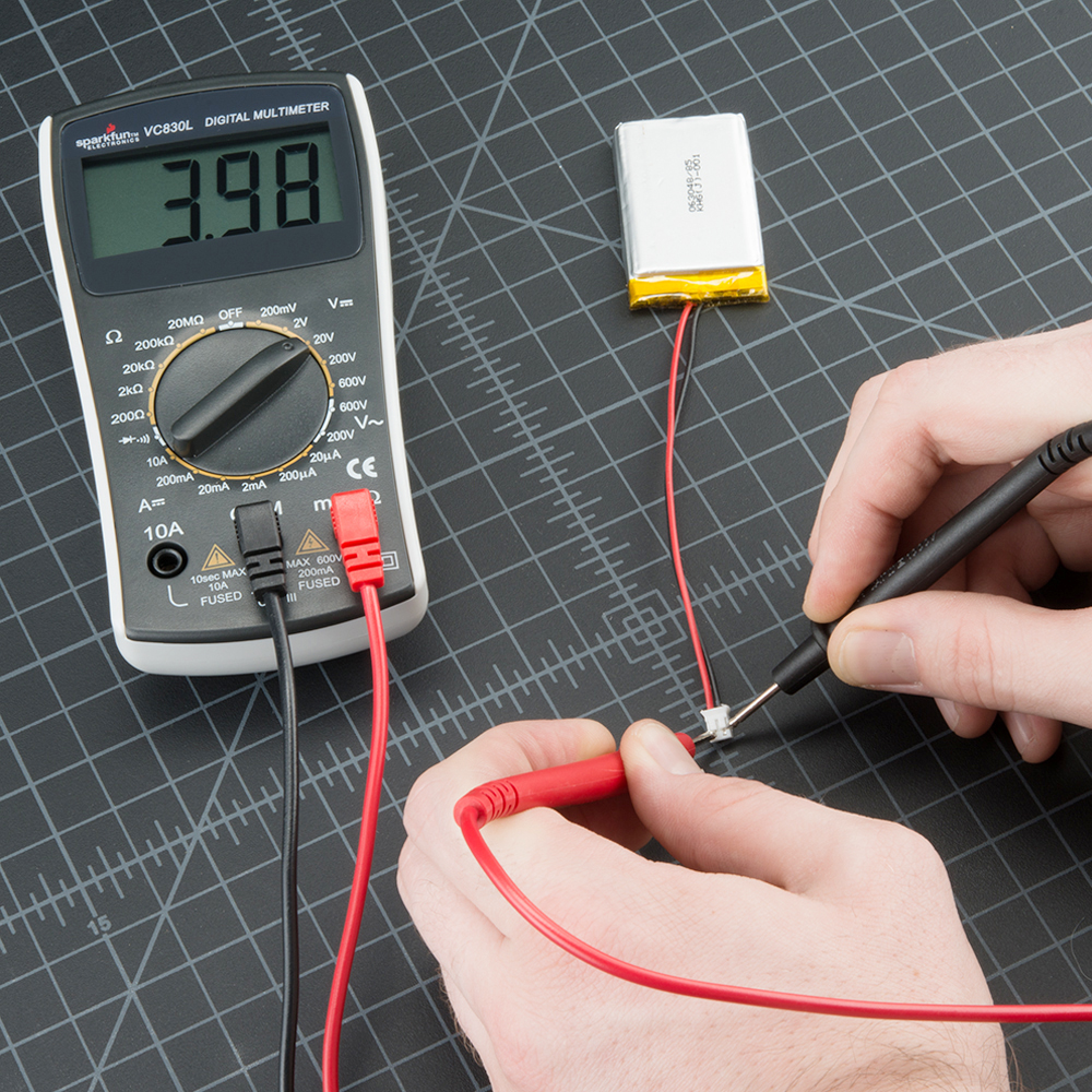
To test this battery we need to place a volt meter across the positive + terminal and negative - terminal. Using a volt meter we would simply put the leads on the appropriate terminal. The Red lead normally will go on the positive terminal and the black lead will go on the negative terminal. A volt meter can be either Analog (with a meter showing a needle that moves) or a digital volt meter which just shows digits for the output. Below are photographs of both types the volt meter on the left is an analog meter and the one on the right is a digital volt meter. If the meter needle deflects to the left of gives a negative sign, you have the leads reversed.
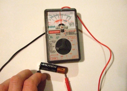
Now Testing the voltage of a battery is illustrated below:
Unlike the oscilloscope tracing of an AC current, the DC current will not show an alternating sweep pattern as shown below:
You note that the wave is all in the positive, where as in the above AC tracing the sine wave goes in the the positive quadrant as well as the negative quadrant.
We use Wattage and the symbol for current ' I ' interchangeably, so as we see in the following examples when we speak of a bulb with a wattage of 5 Watts we are actually saying the bulb uses 5 watts of current.
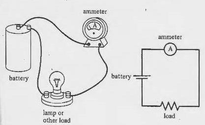
We know the voltage of the battery since we tested it with a Voltmeter. Now what is the Amperage of the battery. Unlike voltage, amperage is determined by connecting the Ammeter in series with the circuit. In this case a light.
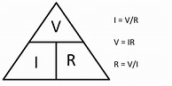
Notice the leads are connected to the battery, however, there is a light in the middle. That is resistance in the line. What will the voltage Be? That depends. The formula is quite simple. We would use Ohms Law, (it's not actually a law but everyone calls it that), which is V = I x R.
Since we do not know what the I (current is in Amps), we either need an Amp meter shown above or use a derivative formula:
Let's assume for the purposes of this discussion that the Amp meter tells us that the current from the battery through the resistor (the light) is 2.66 Amps. Well then the problem is solved V = 2.66 Amp x R. What is the resistance of the light? Again use the formula above, the Ohm's triangle above. If you want to know the value for one of the symbols in the triangle cover it and use the remaining two symbols to tell you what to do. Cover the I we see it is equal to V/R. Cover the V and we see I x R. It works well if you forget the formulas. So if we cover R in the triangle we learn that Resistance (R) = Votage / I (current). So 1.5 VDC / 2.66 Amps that gives us a Resistance of 0.56 but 0.56 what? 0.56 Ohms, named after the discoverer Georg Simon Ohm. Now we know the R and I so let's solve for the voltage left in the battery after connecting the volt meter to the terminals either side of the light. V = I x R, so here we have Volts = 2.66 x 0.56 that give us a little less than 1.48 VDC.
A more practical way to determine the voltage in the battery is take the wattage of the bulb and use the AC formula where V= I / R where W = 2.66 / 0.56 That equals a 5 Watt bulb that gives a resistance in the circuit of 0.56 Ohms.
Let's use a more practical approach. Let's say you have a vehicle and it has corrosion around the lead terminal of the battery. Now your car has a new 12 VDC battery. It is in the dead of winter but your car is hard to start, even with a new battery. Let's use the above formula to find out why.
Corrosion on a battery terminal is between 0.5 - 0/7 Ohms, depending how much corrosion is there. Now a typical starting motor to turn you car engine over takes approximately 100 Amps. Let's use the above formula:
V = I/R
V = 100 / .06
V = 6 VDC That is what is lost in the system due to the corrosion.
Now we take your car battery and subtract from its original 12 VDC - 6 VDC which is used due to the corrosion, you only have 6 Volts DC to start your car. Advise, clean your battery terminals before the winter.
We learned how to make AC current so, let's make a battery. The first thing we need is to decide what appliance we are going to use. Naturally carrying around a car battery to power your cell phone, watch or flashlight is not practical. Neither is connecting a series of AA batteries a practical approach to starting your car.
We have to under stand electron theory first. A battery with a concentration of electrons at one terminal and an excess positive charge at the other, is a storehouse of electric energy. If a metal wire is connected from one terminal to another, electrons will run off the negative terminal into the wire and out to the wine into the positive terminal. Negative - electrons seek + positive charged items, such as a terminal. See that battery above, the positive terminal is in potential state to receive electrons from the negative terminal which in that case was a carbon rod. The electrolyte solution causes a chemical reaction which is more easily explained in the following.
Any source of electric energy must get the energy from somewhere., The battery get enerby from the chemical reaction. The generator get energy from the work done in turning it. Any such source can be rated in terms of the electric enery it produces foe rach unit of charge separated. This quantity -the energy per unit charge converted from some other form to electric-is call eht emf of the source. The letters emf stand for 'electromotive force', but this is a very poor name, left over from the days when electricity was not well understood. the emf of a source is not a force, it is a potential, a value of energy per unito of charge. It is measured in joules per columb (volts) as expressed as:
emf = ▲Ee / q
The common zinc-carbon dry cell shown above, or the newer alkaline cell, produces and emf of 1.5 volts regardless of its size. A large cell produces more enerby by separating more charges, but the energy added to each coulomb separated depends only on the kind of chemical reaction that does the job. If you calculator uses a 9-volt battery, it is made of six dry cells, each adding 1.5 joules of electric energy to each coulomb that passes through it.
Charges flowing out of the positive terminal of a battery is at a high energy level, when it enter the negative terminal, its energy is low. Somewhere in the circuit, the energy of the flowing charge is converted into other forms. When a bulg is let, the electric energy becomes heat and light.
In a car battery the electrolyte is a combination of water and acid which is poured between plates. The below description and photos demonstarte how electric energy is created by the reaction between the metals and the acid-water mixture.
Lead Acid batteries were introduced back in 1859 and since then, there has not been much change in the composition and manufacturing technique of lead acid batteries. With all the alternative sources of energy being explored and implemented; we are seeing a rising trend in demand of Lead acid batteries. However, these batteries have a high cost and you will need to spend quite some money to replace them (average life of commercially available deep cycle batteries is 1.5-2 years) when they die out on you. This is where we come in with our guide on how to rebuild a battery from your dead battery. The construction is quite simple actually.
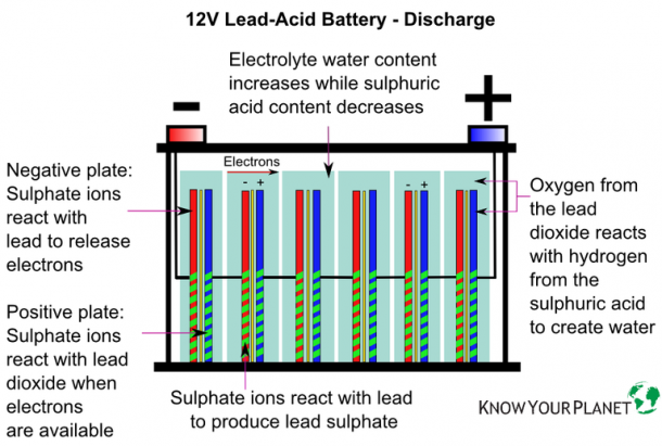
Lead-acid batteries consist of (at least) two lead plates separated by a chemical solution generally made of 30-50% sulfuric acid, a.k.a. “battery acid.” When fully charged, the battery’s negative plate is solidly lead, the electrolyte is concentrated sulfuric acid, and the positive plate consists of lead dioxide.
When the battery is discharged, electrons move through the solution from the negatively charged plate to the positively-charged plate. If the battery has become fully discharged (“dead”) then both plates will have become lead sulfate, separated by a solution of water.
When a car battery is in a discharged state, we can recharge it and this is what happens electro-chemically within the battery. The charging current changes lead sulphate into spongy lead, and acid is formed. The acid is mixed :with the diluted electrolyte outside of the plates. As the charging proceeds the active material shrinks or contracts, and the weight of the plate actually decreases on account of the difference between the weight and volume of the lead sulphate and spongy lead. If the cell has had only a normal discharge and the charge is begun soon after the discharge ended, the charge will proceed quickly and without an excessive rise in temperature. If, however, the cell has been discharged too far, or has been in a discharged- condition for some time, the lead sulphate will not be in a finely divided state as it should be, but will be hard and tough and will have formed an insulating coating over the active material, causing the charging voltage to be high, and the charge will proceed slowly. When most of the lead sulphate has been reduced to spongy lead, the charging current will be greater than is needed to carry on the chemical actions, and will simply decompose the water into hydrogen and oxygen, and the cell "gasses. " Spongy lead is rather tough and coherent, it, and the 'bubbles of gas which form in the pores of the negative plate near the end of the charge force their way to the surface without dislodging any of the active material.
Lithium-ion batteries are perhaps the most promising. These batteries consist of a lithium cobalt oxide cathode paired with a graphite anode. The addition of chemical substances such as phosphates and titanates has been shown to lengthen the lifespan of lithium-ion batteries; likewise, chemicals like lithium vanadium oxide and silicon are continually being tested for their use in improving energy density.
Zebra batteries are relatively new to market and use a chloroaluminate sodium as their electrolyte. While they do boast high energy density, they have a relatively low power density and must be heated in order to charge.
Nickel-Metal hydride batteries are a mature technology. They have a very high energy density. The metal portion of the electrode can be made up of many substances, from neodymium to lanthanum to cerium. Other commonly-used metals include nickel (hence the name), cobalt, aluminum, and manganese. The electrolyte used in these kind of batteries is alkaline, typically potassium hydroxide.
Just an aside, if you want to become a millionaire invent a device to hold AC current as a battery holds DC current. Engineers have been stumped for years trying to figure that one out.