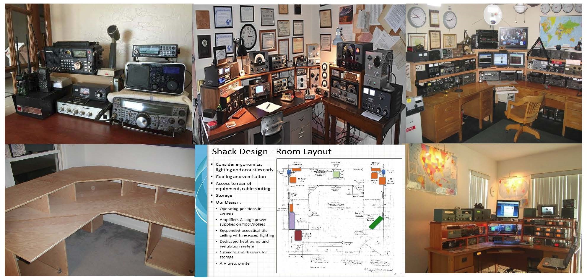
DESIGNING YOUR RADIO 'SHACK' ROOM
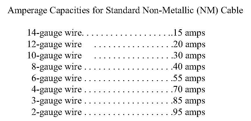
Well, the above shacks have already been built. When constructing your radio station or reconstructing the station, pay particular attention to the availability for three items. First electric service; make sure your have plenty of voltage and amperage to accommodate your current equipment and the strong possibility of adding more radios or accessory equipment. Second, access to the outside world. Make sure you have a way to get your feed line(s) and ground line to the outside. Third, make sure you have plenty of AC outlets. Just because you are using a surge protector with many outlets, make sure your feed lines from the service panel populate the outlets. Remember, If you are drawing 17 Amps, a 15 Amp breaker will not suffice. Also, if you are using or intend to use an RF Amplifier you need to run a 240 Vac line. That will require a dual 30 Amp breaker in the service panel and a run of ORANGE 30 AMP wire, which contains 10 gauge copper wire conductors. See the belwo panel for
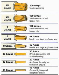
Remember the formula: For amount of Power needed W(atts) = A(mps) x V(oltage) and amount of current needed A = W/V
Try to have at least a couple of feed lines from the service panel dividing up the wall outlets. Remember Watts = Amps x Volts. So, Available Wattswith a 15 Amp breaker x 120 Volts this circuit has only 1800 Watts available. So two separate feed lines populating your outlets you have 3600 Watts available. So if you have three duplex outlets on one circuit and three on another circuit you should have enough to operate your equipment.
Now once you have selected your potential site, you are only limited to the physical space you have available and your imagination. A beginning Radio Room or 'Shack' might be a desk that is large enough for the radio equipment. You might want to construct a above the desk shelf to hold your second radio, a speaker, antenna tuner, switch or rotor for your beam. Lighting is also important and your particular shack will dictate what the appropriate lighting should be.
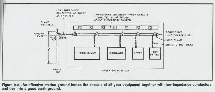
Before you begin populating your desk area for the station, take the time and build a good grounding system. Try to avoid the "cold water pipe" grounding system. If that's all you have you will be forced to use it, but the better system is to snake 'grounding wire' the best ground is one that is connected to a ground rod driven into the earth. The shorter the ground wire to the ground rod the better.
Look at this drawing which will show the installation of the ground system.
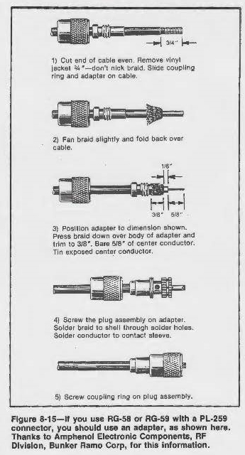
The following left hand sketch are long wire (Dipole) configurations and the formula for specific Frequencies and to right is a diagram of how to add a PL-259 connector to coax feed line:
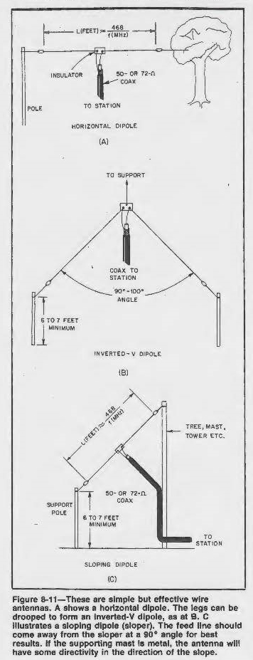
Now for the formula for construction of a 20 Meter Dipole for a resonant frequency of 14.300 MHz:
L = Length
486 = Constant
f = Frequency in MHz
____________________________
L(ength) = 486/f
L = 486/14.300
L = 33.98 Feet = 33' 11"
You would cut the dipole wire to the length of 33' 11" and secure that length between the insulators. In the center of the Dipole wire you would cut the wire in half and connect another insulator. Look at the above drawings. Then you would attach your feed line to the two lengths of the Dipole. The inverted 'V' Dipole should have an angle between 90 - 100º.
Therefore the formula for converting Frequency to Meters is:
c = the speed of light, 3.00 x 10⁸ meters per second
f = the frequency of the wave in hertz
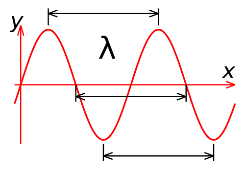
 = wavelength of the wave in meters
Hence: f = c / and = c/f
From these equations you may realize that as the frequency increases the wavelength gets shorter. As the frequency decreases the wavelength get longer. Suppose you are transmitting a radio signal on 7.126 MHz. What is the wavelength of the signal? We first must change the frequency to hertz 7.125 MHz = 7,125,000.
= c / f = 3.00 x 10⁸ mtr per sec / 7.125 x 108
= 300,000,000 m per sec / 7,125,000 = 42 Meters
Again: A frequency of 3.725 MHz
= 300,000,000 mtr per sec / 3,725 = 80.5 Meters
Popular Amateur Radio Frequencies are found in the 10, 15, 20, 40 and 80 Meter Bands.
So the Frequency for those bands are generally:
10 Meters = 28.000 - 29.700 MHz
12 Meters = 24.890 - 24.990 MHz
15 Meters = 21.000 - 21.450 MHz
17 Meters = 18.088 - 18.168 MHz
20 Meters = 14.000 - 14.350 MHz
30 Meters = 18.088 - 18.168 MHz
40 Meters = 7.000 - 7.300 MHz
80 Meters = 3.500 - 4.000 MHz
Check with the ARRL and download the latest U.S. Amateur frequency and mode allocations.
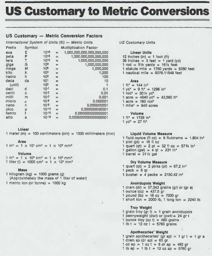
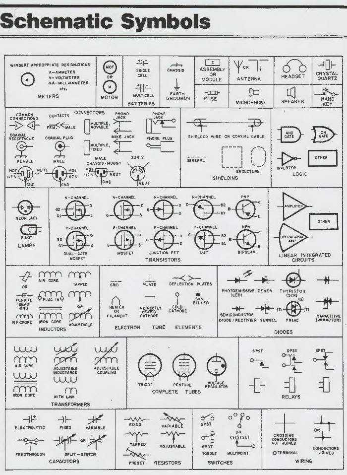
The last two pages are U.S. Customary to Metric Conversions and following that are commonly used Schematic Symbols.