HALL - CARPENTER, CO.
By Edwin T. Scallon, Copyright © 1990, 1995, 2008 All Rights Reserved
ACCIDENT RECONSTRUCTION AND BAC CALCULATION PROGRAMS
CRITICAL SPEED DERIVED FROM CENTRIFUGAL YAW MARKS
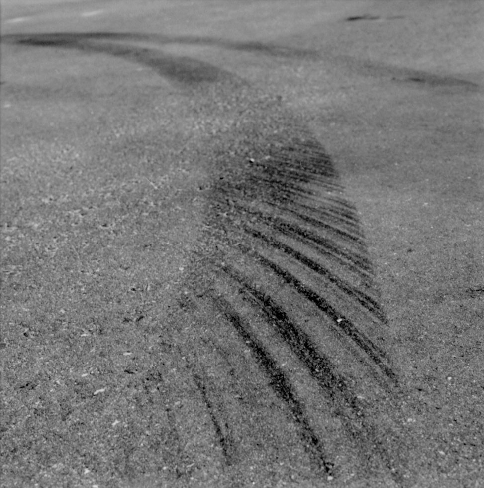
Critical speed Yaw marks are what's left by a tire that is still rolling but is simultaneously sliding laterally. They are always curved and initiated by a steering input. If you're driving too fast into a corner you'll create a set of yaw marks. Yaw marks have distinct striations, stripes or streaks induced as the sidewall is dragged over the road. These marks are aligned in the direction of the spin, usually parallel to the car's axle. In order to obtain a path radius, we first measure a chord of the arc left by the outside front tire. A chord is any line that cuts the arc at two points. • The chord beginning is right after the rear tire mark crosses over the front tire mark. Chord lengths should be between 30 and 50 feet. Yaw marks are a result of the centrifugal force in a turn when it overcomes the centripetal force. Centrifugal force increases with the curve and vehicle speed. Once the centrifugal force overcomes the centripetal force, which keeps the vehicle going in the curved direction of the turn, the tires loose the necessary friction to keep the vehicle from spinning. Once the vehicle enters the spin or yaw, the rear tire tracks to the outside of the front tire and as such while the tire is rotating and sliding the skuff mark left on the road surface has the distinct "hash nark" striations which usually are parallel to the direction of travel when breaking. The same striations left in a yaw scrub when no braking are parallel to the vehicles axle.
Below is a perfect example of a centrifugal yaw mark while the vehicle was breaking:
To make the necessary calculations, when measuring a yaw mark, the following items of information are needed:
1. Confirmation tht the marks observed on the road were indeed yaw marks
2. The grade in the direction of slippage
3. The coefficient of friction of the road surface
4. The radius of the curve followed by the vehicle.
A yaw mark is a scuffmark made on a surface by a rotating tire which is slipping more or less parallel to its axis. Yaw marks have characteristics that distinguish them from other tire maraks, and are seen in the above photo. Sometimes yaw marks are called critical speed scuffmarks, centrifugal skid marks or sideslip marks.
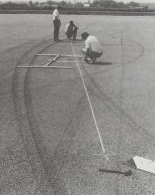
If you use a drag sled or actual test vehicle skid marks, the road grade is contained within the dynamics when using those instruments. You will need a tape measure which is capable of measuring over 100 feet. At the scene, measure the chord (C), record the distance in feet then and mark that area with chalk or other material identifying the location of the chord. Now locate the middle of the chord and measure the distance from the curved yaw mark to the location of the chord this is known as the middle ordinate (M), likewise record that measurement in feet. You can use inches if you choose, but you need both the chord and middle ordinate using the same measurements both in feet or both in inches. When measuring the middle ordinate, make sure that the middle ordinate measuring tape is at a 90° to the chord.
Look at the below diagram and photo to visualize what you would see at the seen:
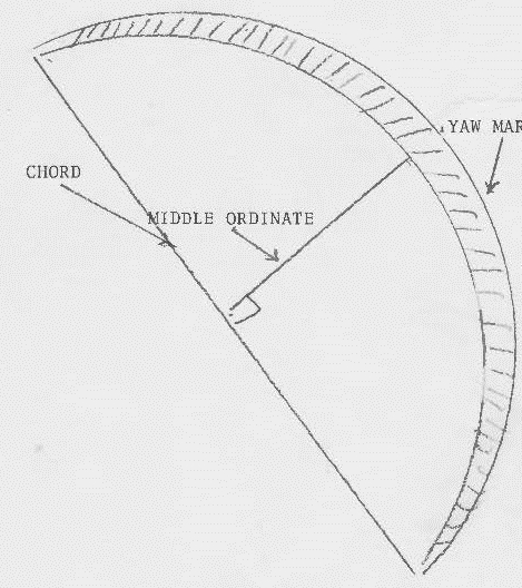
The next step is determining the Radius (R) of the curve. Use the below formula to determine the radius:
R = C2 /8M + M/2
Once the data is recorded and the Radius is calculated enter it into the below Critical Speed formula:
S = 3.87√R*f
In an earlier session we calculated a drag factor for a 10 year old rural asphalt road and found that the drag factor was 0.8g. So lets use that road and assume the drag factor was accomplished in the direction of the yaw. We then measured the Chord (C) and found it to be 160 feet from beginning to end. We then measured the Middle Ordinate (M) and found it to be 15 feet. We will now determine the radius of the curve (R) using the above formula and our data.
R = C2 / 8M +M/2
R = 1602 / 8(95)/2 + 95/2
R = 1602 / 760/2 + 95/2
R = 25600 / 380 + 47.5
R = 25600/815 + 47.5
R= 31.41 + 47.5
R = 78.91
Next we use the radius and calculate the Critical Speed of the vehicle using the Critical Speed Formula:
S = 3.87√R * f
S = 3.78√78.91*.08
S = 3.78√63.12
S = 3.78*7.94
S = 30 Mph
There is computer simulator available to check your math. I caution you, that the minimum speed formula is not adjustable, but the critical speed formula is of some use in checking your math. It will indicate if your calculations are very far off. It is located at:
http://www.ohiopd.com/skidmarks.php
Try the above link and see if your math corresponds to the computer model. Remember, we normally drop the digits to the right of the decimal point.